AXS Series
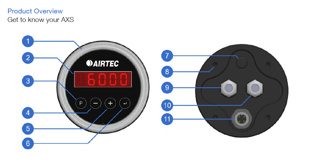
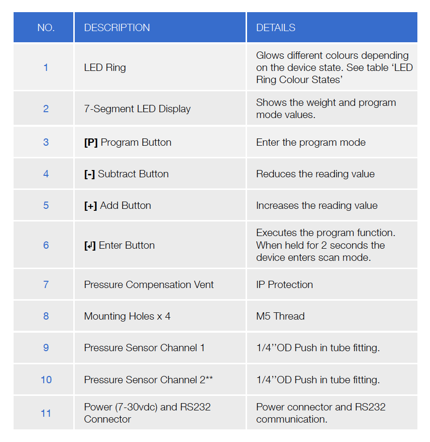
The LED Ring changes colour depending on the set target weights. Blue shows the gauge is under the target weight, Green shows the gauge is on target weight, and Red shows that the gauge is over target weight.
Authorised calibrators will have access to the digital lock codes either through the calibration login of the SmartOBM mobile app or with their calibrator login on the TruckOBM portal.
1. Press and hold the [P] button until the word LOC appears on the screen.
2. Using the [-] and [+] buttons, scroll through until you reach your 5-digit lock code then press
[ ]. If correct, the word UNLOC will appear on the screen.
3. Press the [P] button to enter the program mode normally. See pages 19 - 24 for more information on the Program Modes.
Fluctuation / Erratic Readings
Electronic Height Control Valves can give erratic readings - try lowering suspensions with the in-cab pendant/remove and re-inflate to drive ride height, to get a stable reading. Calibrate the gauge using the same process.
Fluctuation with the weight readings can be caused by worn height control valves not settling in the same positions, check for leaks/worn linkages.
Dump Test Procedure
A dump test can be carried out to troubleshoot fluctuations issues.
Use an airbag dump valve and lower airbag pressure, gauge readings should go down as the airbags deflate.
When the airbags are deflated, re-inflate the airbags back to ride height. The gauge’s reading should come back to the original value.
Calibration must be done by an authorised Airtec Technician and a Calibration Log must be completed and emailed to: smartobm@airtecaustralia.com.au
How to Obtain an Accurate Calibration Reading
- Keep the engine running to provide air to the suspension system.
- Park the vehicle on level ground.
- Release vehicle brakes. If the trailer is attached, release the trailer brakes.
- Exhaust the air from the suspension and re-inflate the airbag suspension to the correct rise height.
- You will know you have the correct calibration when the weight shown on the AXS unit is the same as the weighbridge value. Note: consider a 0.2% margin or error between values.
Drive the full combination onto a split weighbridge to observe each axle group’s weight when empty (Tare Value). Enter the bridge’s Tare weights into the gauges LO value fields and store
with the [ ] enter button.
Ideally, fuel tanks are low on fuel, to make drive & steer reading more accurate.
If you are unable to enter values on the weighbridge, drive to an area of flat road where the values can be added safely, with wheels chocked and brakes off.
Load the combination to its max load and ensure your fuel tanks are full, to calibrate when loaded (HI Value).
Repeat procedure on the split weighbridge and enter loaded weights into the gauges HI value and store with the [ ] enter button.
Complete the Calibration OBM checklist and submit to Airtec Corporation.
It is the responsibility of the fleet manager to ensure that their fleet is compliant and calibration reports are obtained and up to date.
AXR In-Cab Display
Congratulations on purchasing your Airtec AXR wireless in-cab remote.
The AXR Remote can be integrated with the AXM or AXS Truck Scales to remotely display load weights. To display the weights for each axle group and Gross Vehicle Mass from inside the cab simply touch the button on the front of the Remote Display.
The AXR Remote has a very robust polycarbonate and aluminium body with a tough polycarbonate face plate. The display is the same super bright LED used in our AXL/AXM truck scales and can be seen from several meters away; day or night.
The remote is easily mounted inside the cab with a simple magnetic mount.
Please note, AXM units require a firmware of 2.14 or higher to integrate with the AXR.
Electrical
Input Voltage 7 - 32V
Power Consumption
Typical Average 100 mA @12V DC
Protection
Reverse and Over Voltage Protection
Environmental
Operating Temperature - 40 to + 85°C
Dust and Water Ingress
IP66
Mechanical
Display
5 Digital 7-Segment LED
Dimensions
80mm x 80mm x 40.6mm (HxWxD)
Materials
ASA Plastic Base
Polycarbonate Cover
Communication
Wireless Bluetooth 5.2
Wired RS232
Installation must be completed by an authorised Technician.
Mounting the Unit
Mount the unit in a suitable position in the cab. The unit must be mounted so the unit is out of direct sunlight.
The remote comes with Airtec’s AXSM001 Magnetic Mount. For more mounting options, our remote is compatible with most magnetic phone holders.
AXM & AXL Series Generic Support
Troubleshooting FAQ's
Possible Cause: Invalid calibration. Caused by “LO” and “HI” set at the same time either empty or full.
Solution: Recalibrate “LO” value at unladen/empty weight and “HI” value at laden/full weight.
Possible Causes: The calibrated weight of the “LO” value is too close to the calibrated weight of the “HI” value.Solution: Recalibrate the “LO” value at minimum/empty weight and “HI” at maximum weight.
Probable cause:The gauge wasn’t calibrated or was set with incorrect weight on the weighbridge.
Solution:Keep the engine running to provide air to the suspension system. Park the trailer on the level ground. Release trailer brakes. Exhaust the air from the suspension and inflate to correct ride height.
Probable cause: The gauge is not connected to the air-bag suspension.
Solution:Check the air-line connection.
Probable Cause: Display Auto OFF timer mode not set.
Solution: Set display auto OFF timer.
Probable Cause: The time value set for the display auto OFF timer mode is too low.
Solution: Adjust or increase display timer mode
Probable Cause: Check if unit is connected to power.
Solution: Check the power circuit. If the voltage is below 8 DC the unit will not function correctly. Test the power source with a voltmeter. The gauge must be connected to a switched source to allow occasional software reboot.
Probable cause: Check if the polarity is correct
Solution: The red/brown wire must be connected to positive, and the black to negative.
Probable Cause: The height control valve (HCV) is malfunctioning or broken.
Solution: The HCV is not functioning correctly, the air pressure applied to the suspension system could be inconsistent.
Probable Cause: The height control valve (HCV) cannot supply air to the suspension system.
Solution: Set unit into Pressure Gauge Mode to display actual air pressure). Then, check and replace ride height control valve.
Calibration Support
1. Keep the engine running to provide air to the suspension system.
2. Park the vehicle on a level ground.
3. Release vehicle brakes. If trailer is attached, release trailer brakes.
4. Exhaust the air from the suspension and re-inflate the air bag suspension to the correct ride height.
5. Your will know you have the correct calibration when the weight shown on the AXMAXL unit is the same as the weighbridge value.
Consider a 0.2% of margin of error between values.
1. Set Tare Weigh – LO VALUE VEHICLE EMPTY
With the AXM201/202 display on:
– Press and hold [P] button until CHAN appears
– Press [P] again and -1- will appear (when setting weights for the first time stay on channel 1 until calibration for channel 1 is complete)
– Press [+] and channel -2- will appear (skip this step if you are calibrating channel 1)
– Press [P] again, the screen should say DECP
– Press [P] button twice to display LO, press once more to adjust the value.
– Adjust display value with [- ] and [ + ] buttons until reading is the same as the weighbridge docket (known as Tare Weight)
– Press ⏎ button to store
– Press and hold [P] until DECP appears
– Press [P] again and -1- appears.
– Use the [+] button to change to channel -2- and press ⏎
– Press the [P] again until you get to LO.
– Press [P] one more time until the weight appears
– Use the [+] and [-] buttons to set the scales to match the weighbridge docket, remembering you are now setting your rear axle or Drive weight.
– Press ⏎ button to store
– Press [⦶] button to exit program mode.
2. Set Max Weigh – HI VALUE VEHICLE LOADED
With the AXM201/202 display on:
Continue the steps above to complete the HI calibration
1. Set Tare Weigh – LO VALUE VEHICLE EMPTY
With the AXM201/202 display on:
– Press [P] button for 2 seconds to enter Program Mode (dECPT will appear on the display).
– Press [P] button twice to display LO, press once more to adjust the value.
– Adjust display value with [- ] and [ + ] buttons, until reading is the same as the weighbridge docket (known as Tare Weight)
– Press ⏎ button to store
– Press [⦶] button to exit program mode.
2. Set Max Weigh – HI VALUE VEHICLE LOADED
With the AXM201/202 display on:
– Press [P] button for 2 seconds to enter Program Mode (dECPT will appear on the display).
– Press I P 1 button 4 times to display HI, press once more to adjust the value.
– Adjust display value with [- ] and [ + ] buttons, until reading is the same as the weighbridge docket (known as Tare Weight)
– Press ⏎ button to store
– Press [⦶] button to exit program mode.

